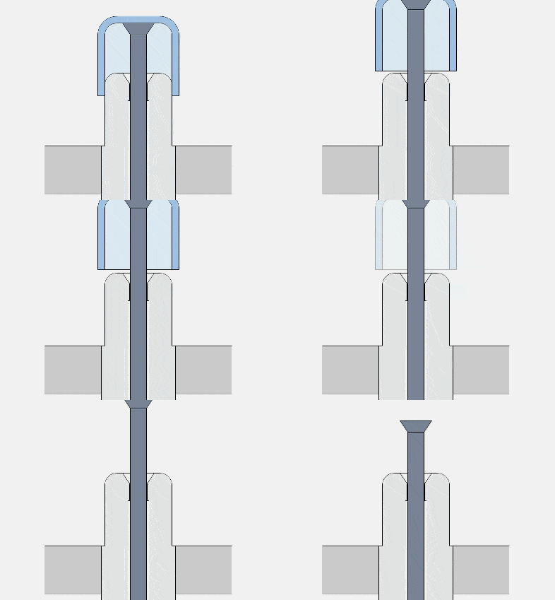
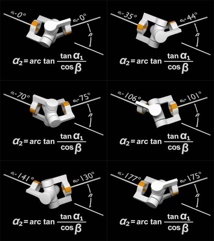
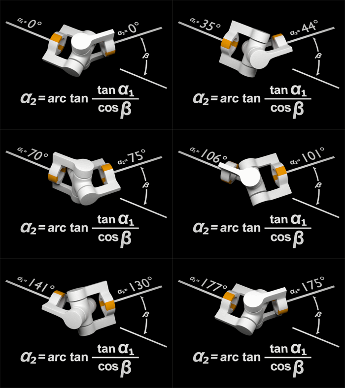
Today, I have compiled 50 common mold structure dynamic diagrams for you, which are clear at a glance, which will help you better understand the mold structure and operation process.
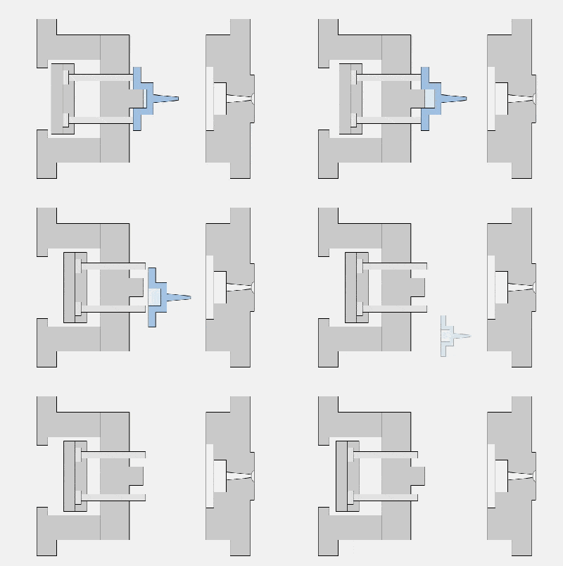
1. Single parting surface injection mould
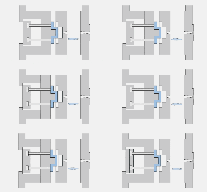
2. Double parting surface injection mould
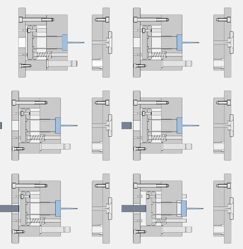
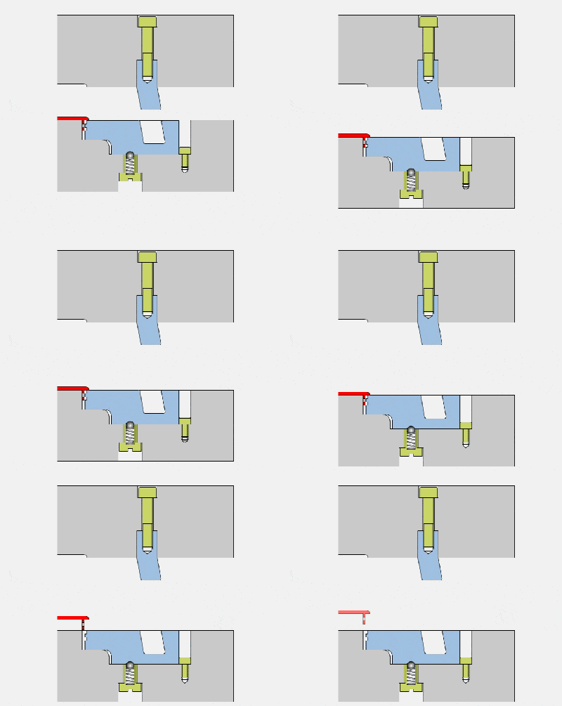
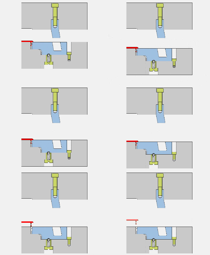
3. Spring reset mechanism
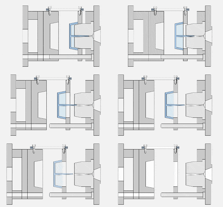
4. Injection mold with fixed mold and ejection mechanism
5. Secondary launch agency
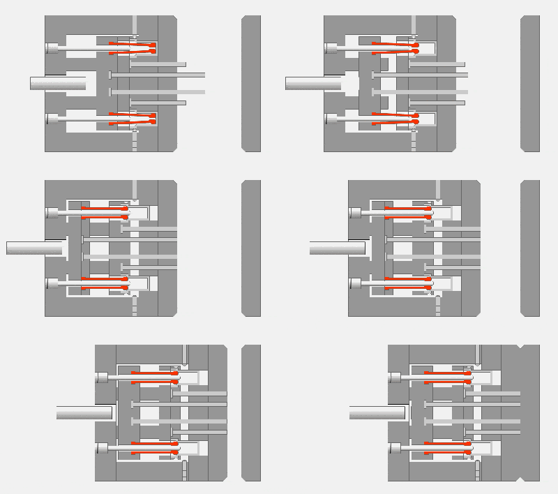
6. Inclined guide column side core pulling-mold opening stroke
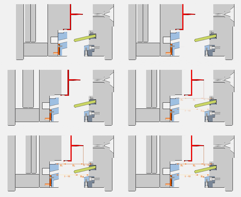
7. Single push plate secondary demoulding mechanism-swing block pull plate type
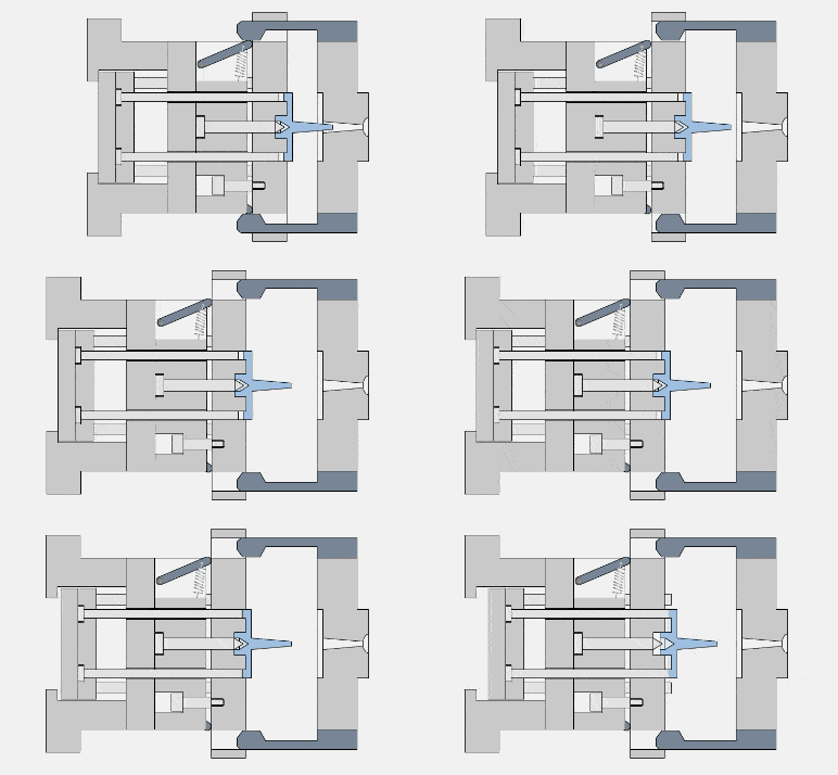
8. Single push plate secondary demoulding mechanism-spring type
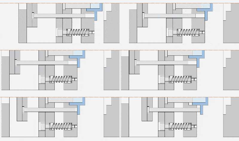
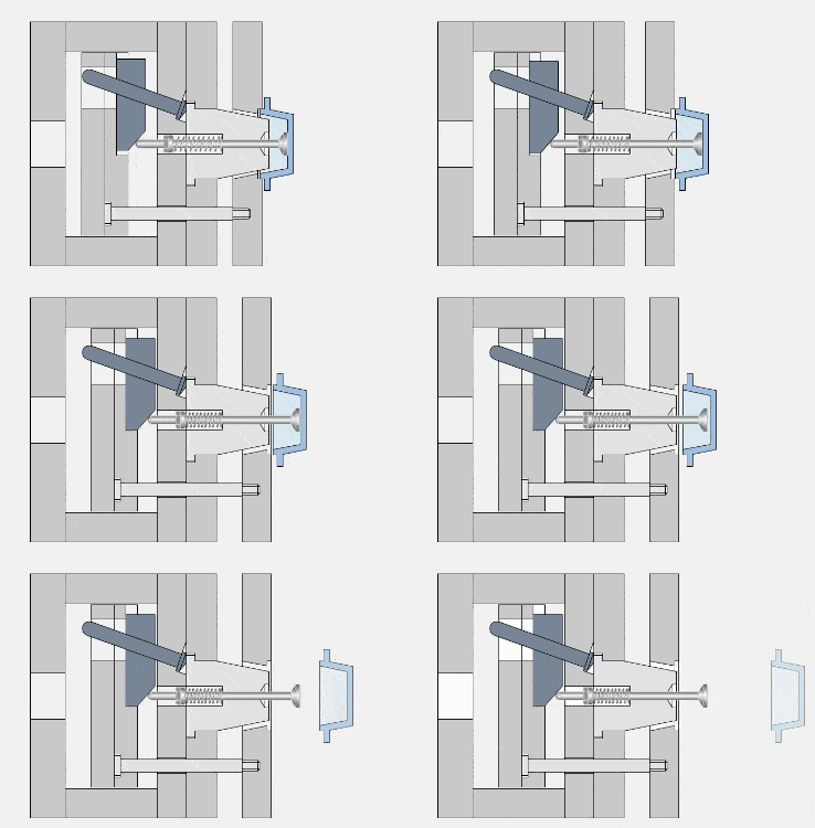
9. Single push plate secondary demoulding mechanism-oblique guide column-slider type
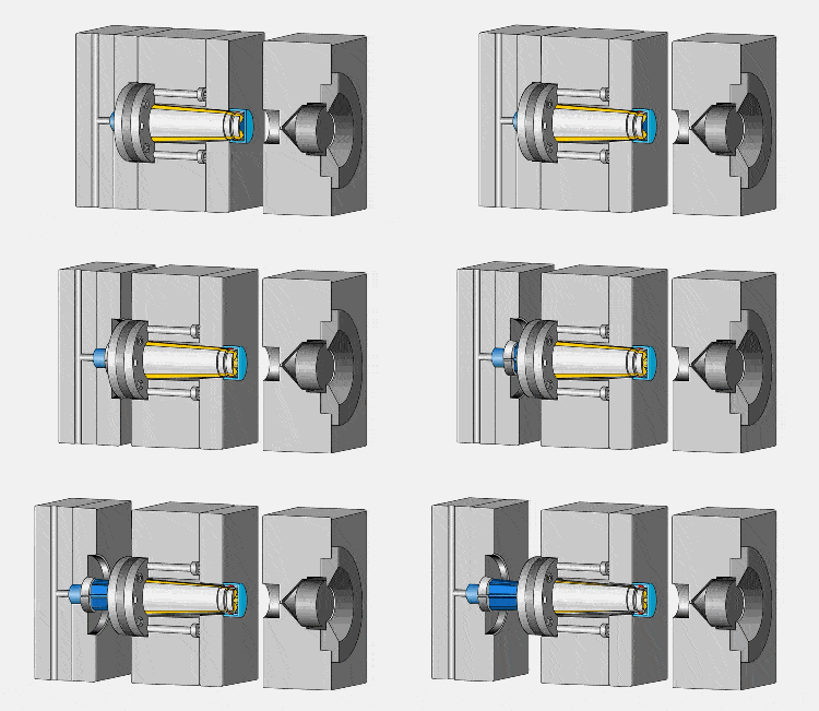
10. Foldable core-three-dimensional
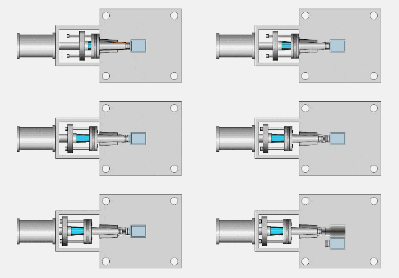
11. Foldable core-plane
12. Lateral parting and core pulling mechanism-slider-1
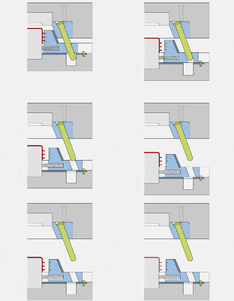
13. Lateral Parting and Core Pulling Mechanism-Slider-2
14. Lateral Parting and Core Pulling Mechanism-Slider-3
15. Lateral Parting and Core Pulling Mechanism-Slider-4
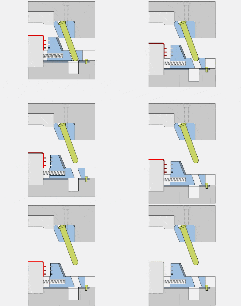
16. Lateral Parting and Core Pulling Mechanism-Slider-5
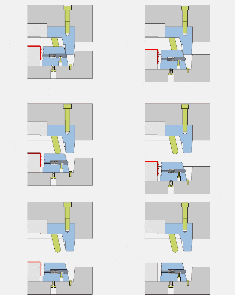
17. Lateral parting and core pulling mechanism-slider-6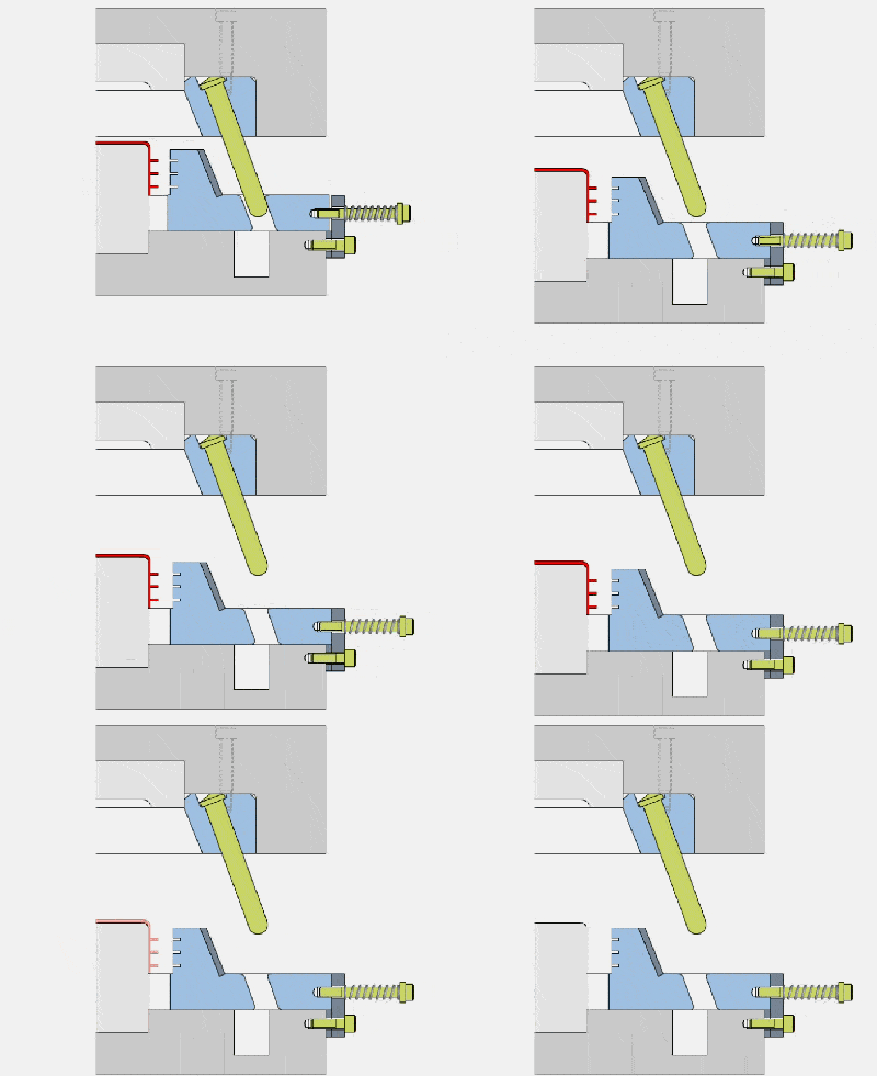
18. Lateral parting and core pulling mechanism-slider-7
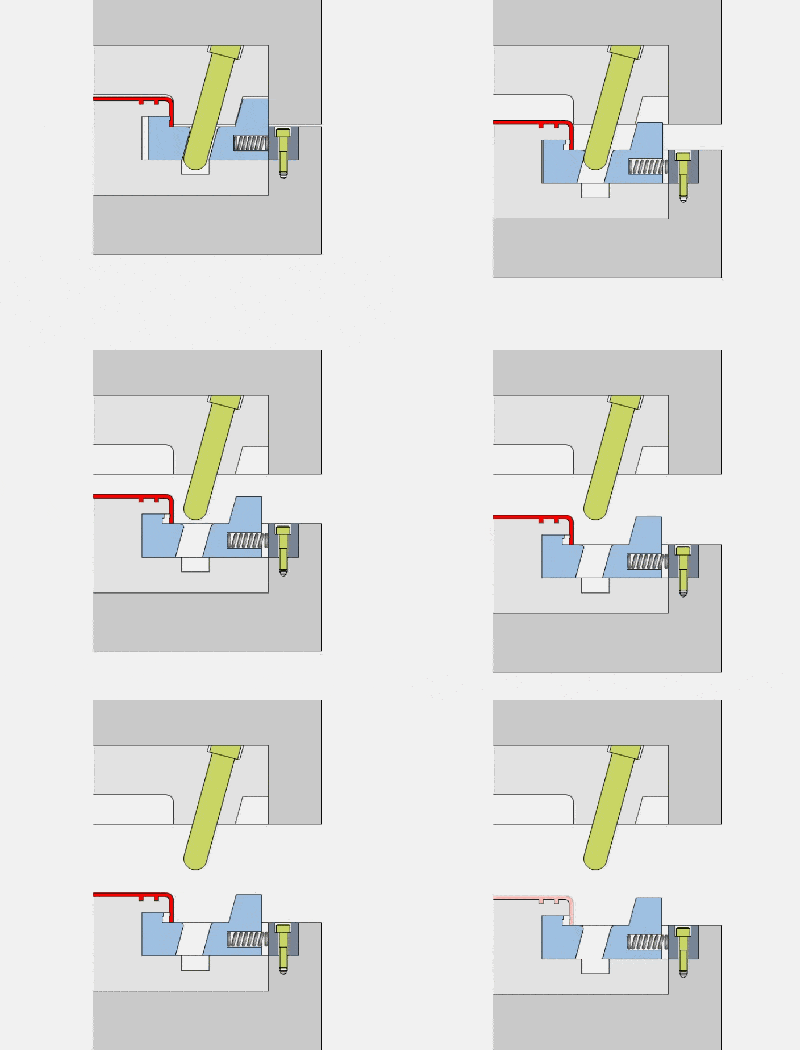
19. Slide block demoulding-external thread
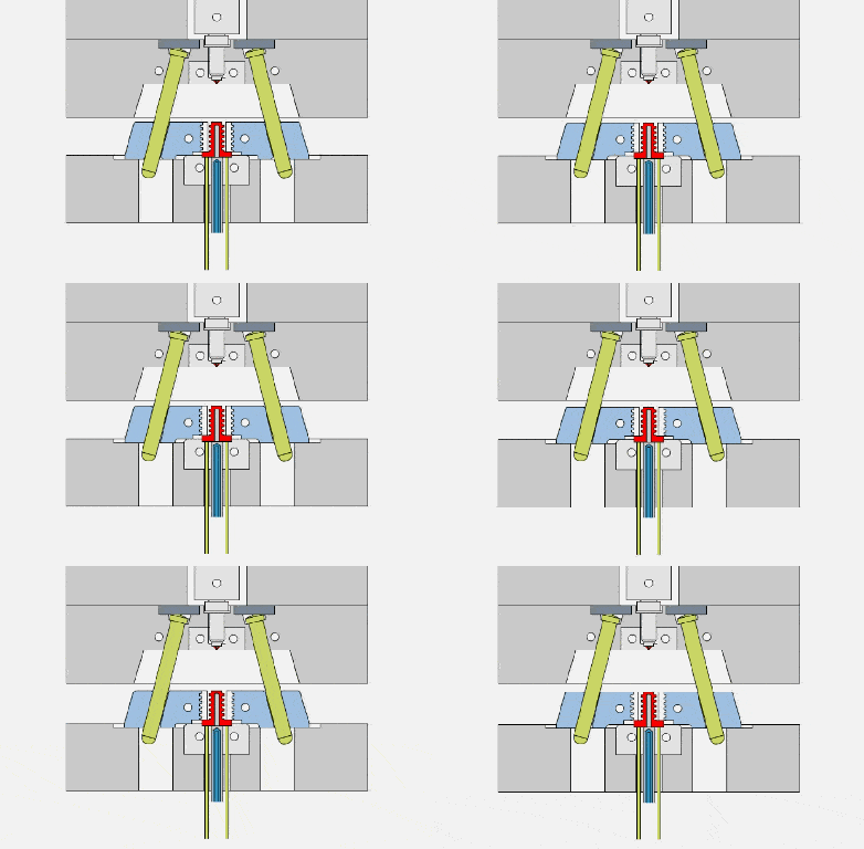
20. Push plate launch
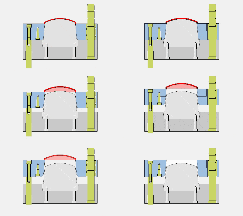
21. Push rod launch-stiffener
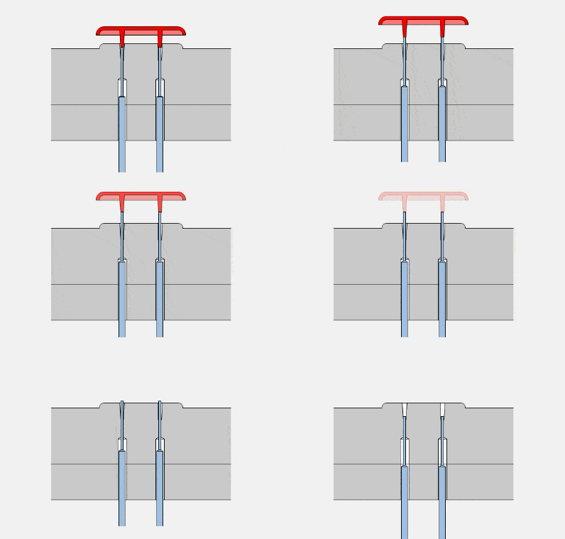
22. Putting out-Inclined
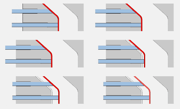
23. Push the tube out
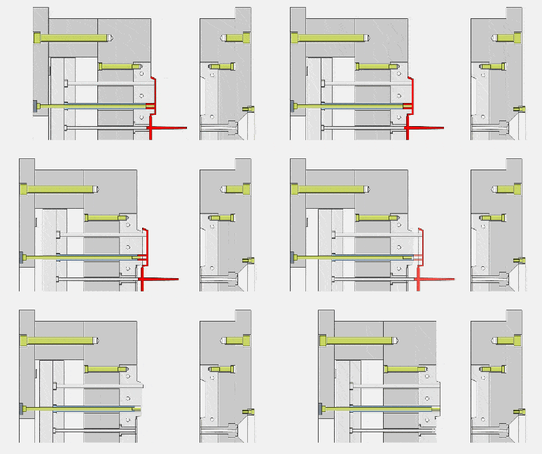
24. Push block launch -1
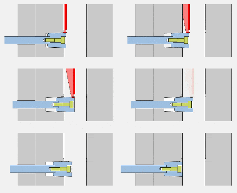
25. Push block launch-2
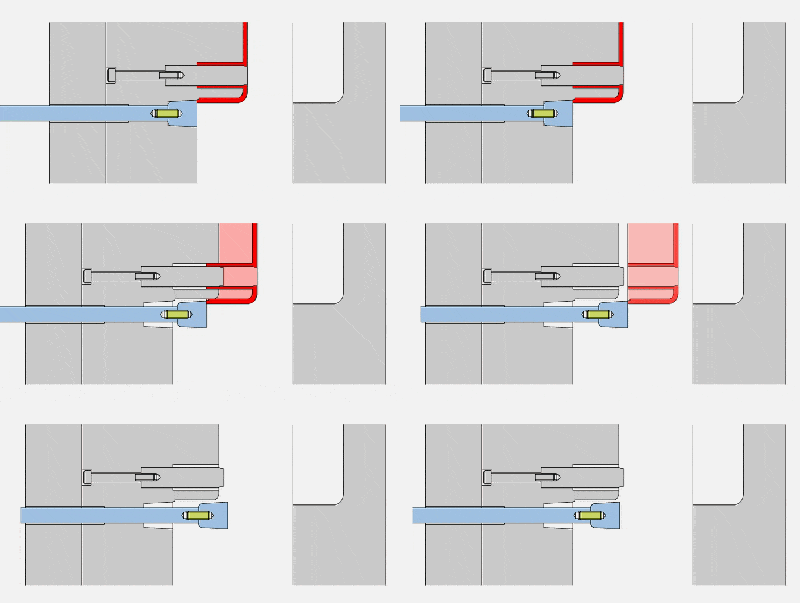
26. Delayed launch
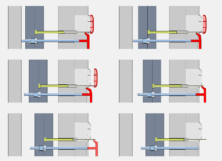
27. Round push rod ejection
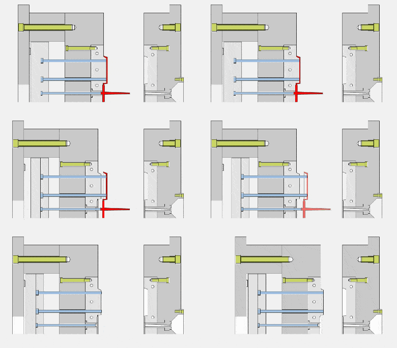
28. Mould base and insert-C type
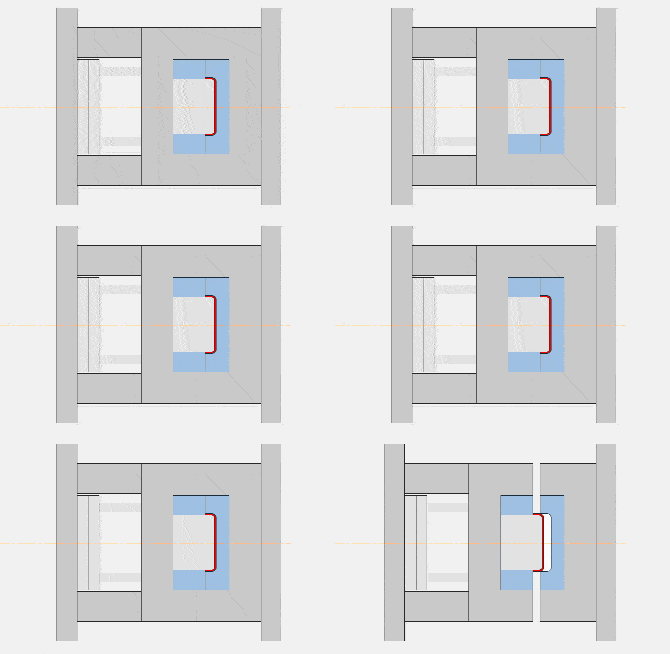
29. The ejection form of the main channel
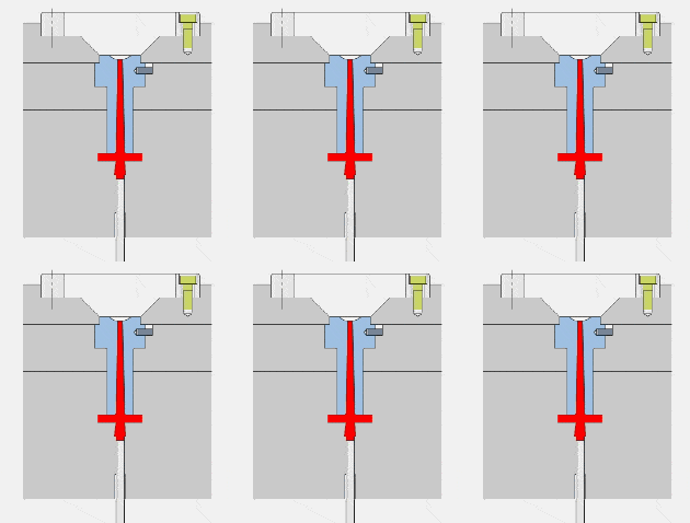
30. Two forms of mainstream
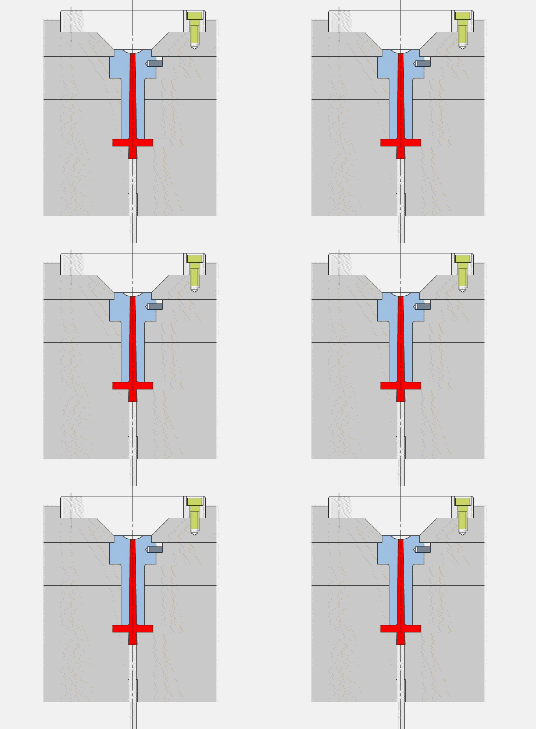
31. Parting surface-vertical parting surface
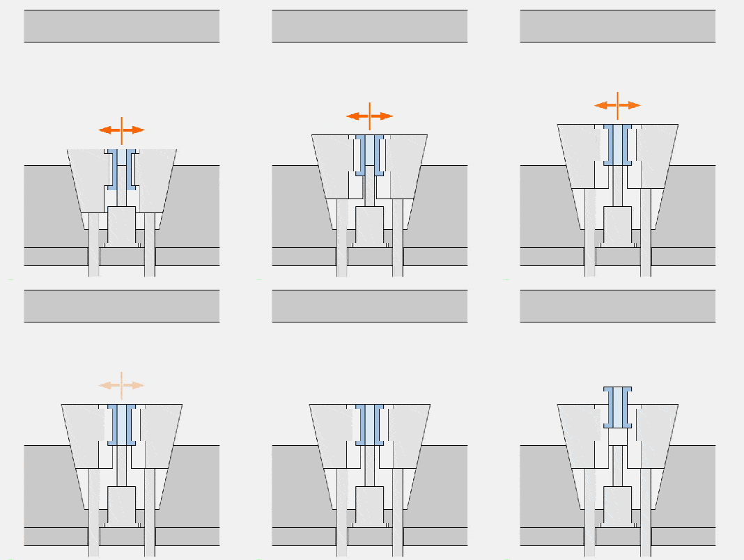
32. Parting surface-Ladder parting surface
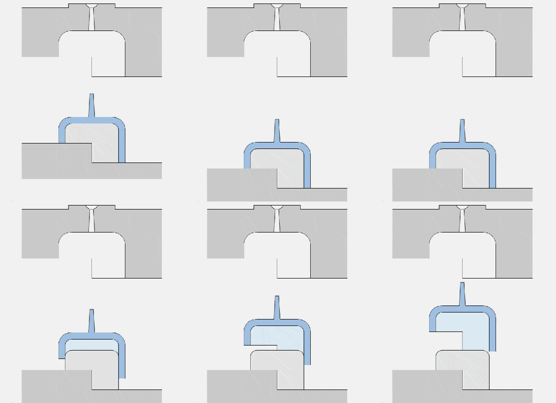
33. Parting surface-plane and curved parting surface
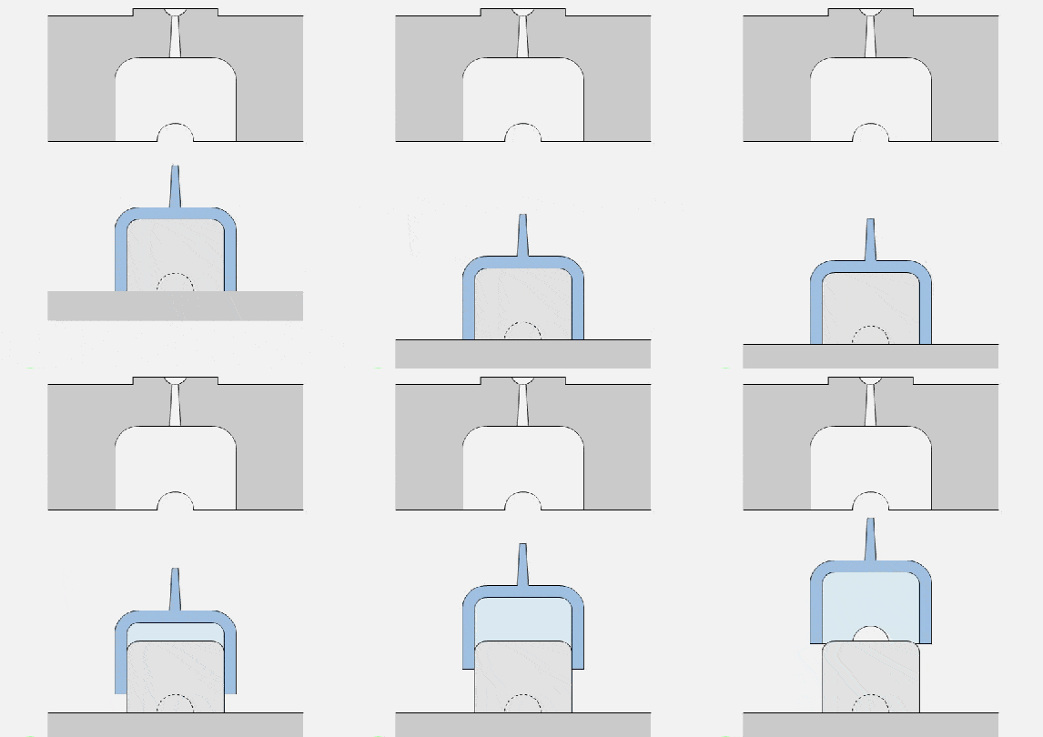
34. Parting surface-horizontal parting surface
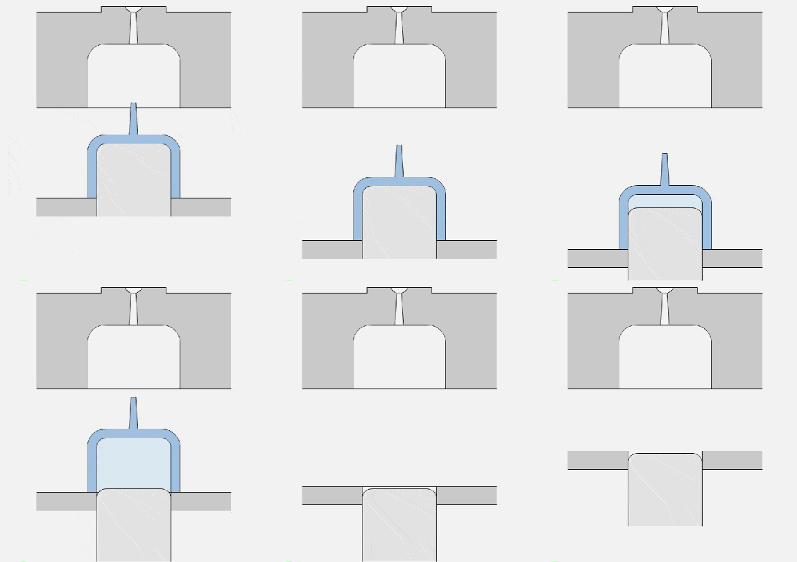
35. Reset lever reset
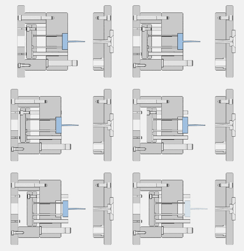
36. Change the position of the parting line-example
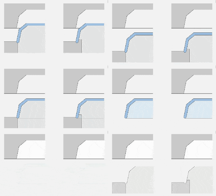
37. Positioning of clamping pin
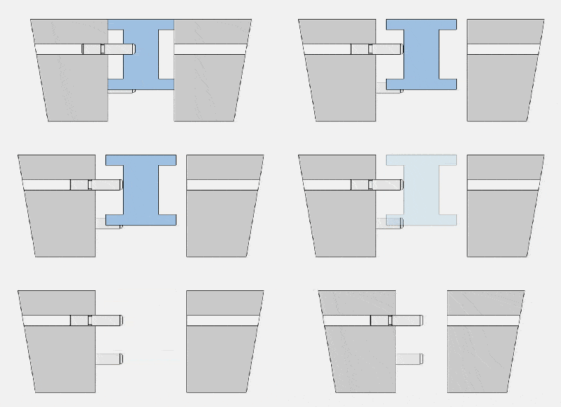
38. Schematic diagram of movable inserts
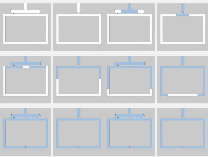
39. The influence of the number and position of the gate on the weld line
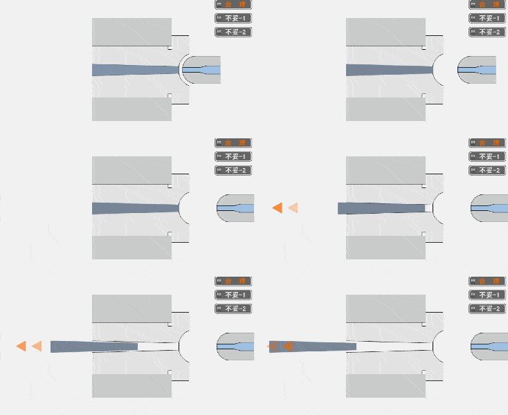
40. Sprue sleeve and nozzle of injection machine
41. Set up a cold trough to increase the welding strength
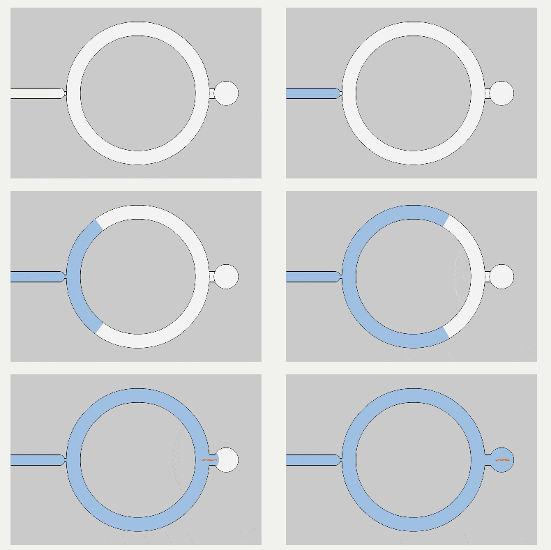
42. Valve type bleed -1
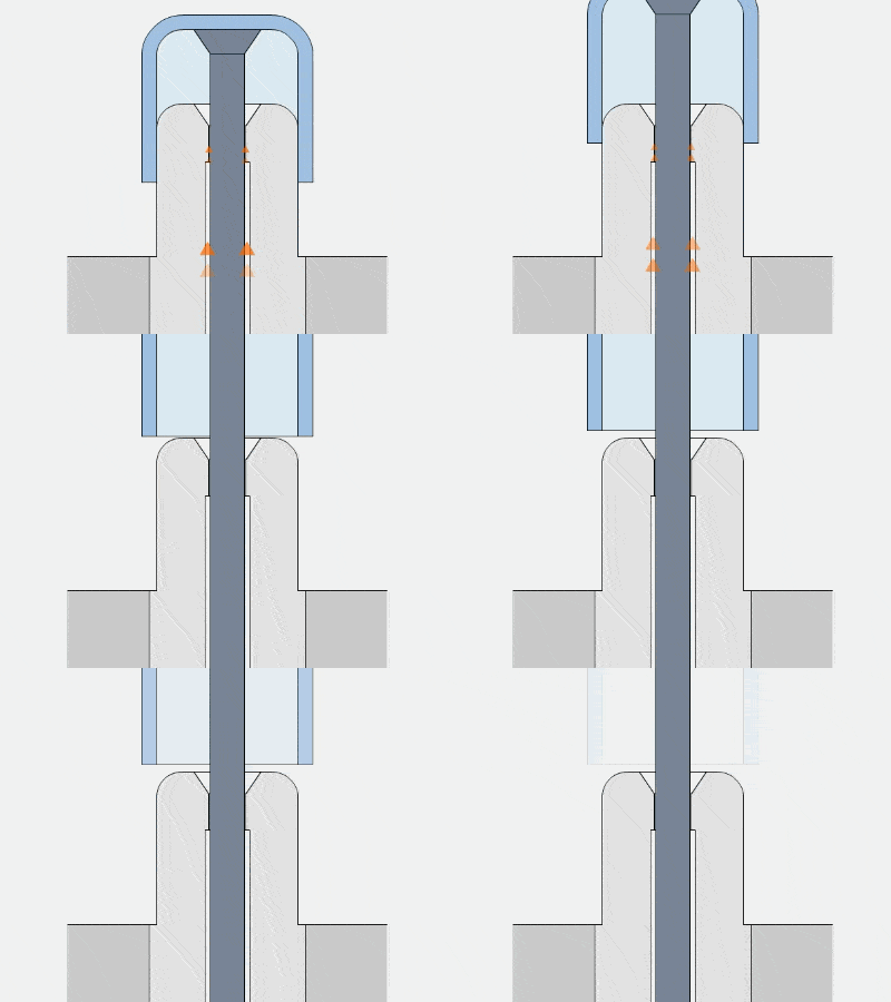
43. Valve type bleed -2
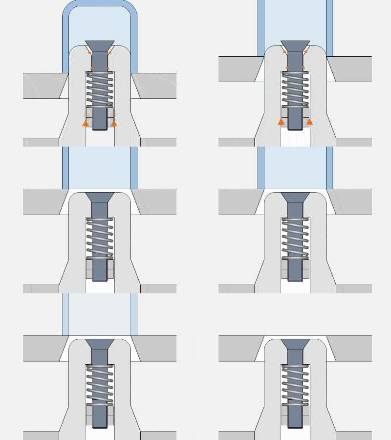
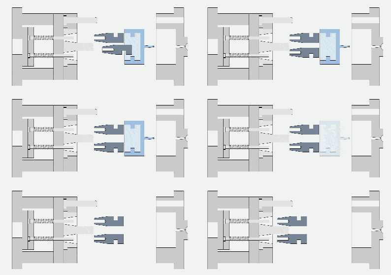
44. Valve push-out mechanism
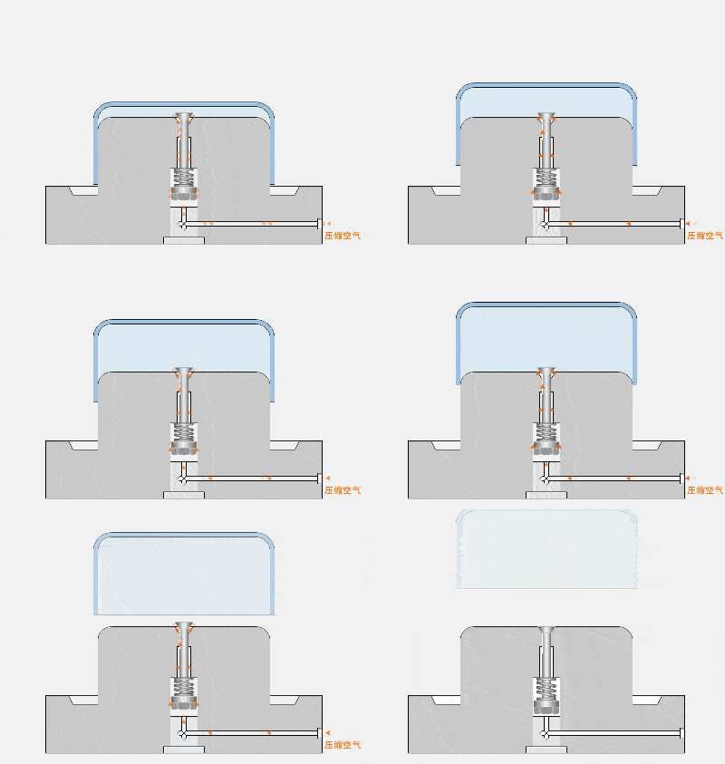
45. Push plate demoulding structure form-1
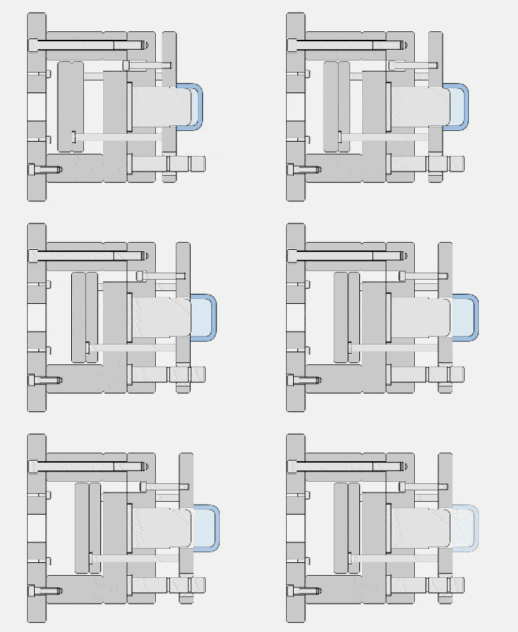
46. Push plate demoulding structure form-2
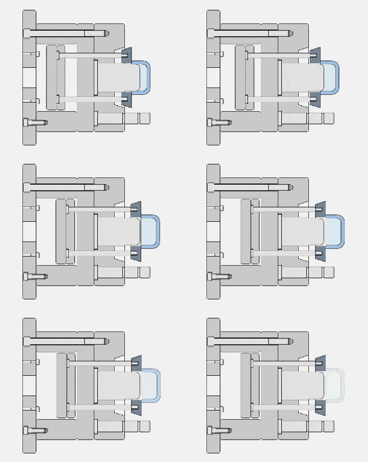
47. Push plate demoulding structure form-3
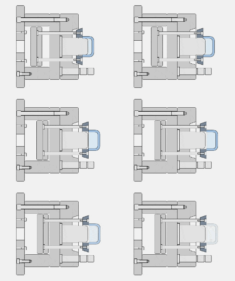
48. The matching form of the push plate and the core
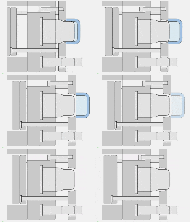
49. Push rod push out mechanism -1
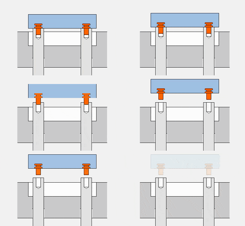
50. Push rod push out mechanism -2
