|
|
|
|
|
|
Punch and die cutting edge dimension and tolerance, directly affects the size of
| |
|
1. The calculation principle of the edge size of the convex and concave dies. The sections of the blanking parts are all tapered.The bright band is the measurement and use part. The bright band of the blanking part is in the large end size, and the bright band of the punching part is in the small end size; The small-end (smooth) dimension of is equal to the punch dimension.In measurement and use, the blanking part is based on the size of the big end, and the hole diameter of the punch is based on the size of the small end.The smaller the profile of the punch is, the larger the profile of the concave die is, resulting in a larger gap.Calculation principle: When designing the blanking die, first determine the size of the edge of the die: take the die as the benchmark, and the gap is taken on the punch, that is, the blanking gap is obtained by reducing the size of the punch's edge.When designing the punching die, first determine the size of the punch edge: taking the punch as the benchmark, the gap is taken on the die, and the punching gap is obtained by increasing the die edge size.According to the wear law of the die during use, when designing the blanking die, the basic size of the die should be close to or equal to the minimum limit size of the workpiece; when designing the punching die, the basic size of the punch should be close to or equal to the limit of the workpiece hole. size.The mold wear reserve is related to the workpiece manufacturing accuracy.The blanking (design) gap generally adopts the minimum reasonable gap value (Zmin).When selecting the mold edge manufacturing tolerance, the relationship between the workpiece accuracy and the mold accuracy should be considered, that is, to ensure the accuracy requirements of the workpiece, and to ensure a reasonable gap value.Generally, the precision of the die is 2 to 4 levels higher than that of the workpiece.For round and square cutting edges with simple shapes, the manufacturing deviation value can be selected according to IT6~IT7 level; for cutting edge with complex shapes, the manufacturing deviation can be selected according to 1/4 of the tolerance value of the corresponding part of the workpiece; for cutting edges The manufacturing deviation value that does not change after dimensional wear can take 1/8 of the tolerance value of the corresponding part of the workpiece and be prefixed with (±).In principle, the dimensional tolerance of the workpiece and the manufacturing deviation of the die edge size should be marked as a one-way tolerance according to the principle of "into the body".However, for the size that does not change after wear, the bidirectional deviation is generally marked.The upper deviation of blanking parts is zero, and the lower deviation is negative; the upper deviation of punching parts is positive, and the lower deviation is zero.Processing method: Separate processing has interchangeability and short manufacturing cycle, but Zmin is not easy to guarantee, and it is necessary to improve processing accuracy and increase manufacturing difficulty.Suitable for: round or simple cutting edge.With processing, Zmin is easy to guarantee, has no interchangeability, and has a long manufacturing cycle.Applicable to: special-shaped or complex cutting edge.1. Calculation method of edge size of convex and concave die 1.Processing method according to punch and die pattern respectively (1) For blanking, set the size of the workpiece as D-Δ. According to the calculation principle, the die is used as the design basis for blanking.First determine the size of the die, so that the basic size of the die is close to or equal to the minimum limit size of the workpiece contour; the size of the punch is obtained by subtracting the minimum reasonable clearance value from the die size; (2) For punching, set the punching size to d+ Δ , according to the calculation principle, the punch is used as the design basis for punching.First determine the punch size, so that the basic size of the punch is close to or equal to the limit size of the workpiece hole; the punch size is obtained by increasing the punch size by the minimum reasonable gap value.(3) The distance between the center of the hole and the center of the hole belongs to the size that is basically unchanged after wear.In the same step, when two holes with a hole spacing of L± are punched on the workpiece, the center distance of the concave model holes can be determined by the following formula.In order to ensure that the possible initial gap does not exceed Zmax, that is, the manufacturing tolerance of the convex and concave molds, it can be selected according to the IT6~IT7 level, or it can be selected from the table (such as the table), but it needs to be checked.If the above formula is not satisfied, but it is only slightly not satisfied; the x-coefficient is to make the actual size of the blanking part as close as possible to the middle size of the tolerance zone of the blanking part, which is related to the manufacturing accuracy of the workpiece. When the tolerance of the workpiece is IT10 or more , take x=1; when the tolerance of the workpiece is IT11~13, take x=0.75; when the tolerance of the workpiece is IT14, take x=0.5.2.Cooperative processing of punch and die is to first make a reference piece (punch or die) according to the design size, and then prepare another piece according to the actual size of the reference piece with the smallest reasonable gap.Features: The gap of the mold is guaranteed by the preparation, the process is relatively simple, and there is no need to check.Moreover, the manufacturing tolerance of the reference part can be enlarged, so that the manufacturing is easy.Applicable to: special-shaped or complex cutting edge.When designing: the cutting edge size and manufacturing tolerance of the reference parts should be marked in detail, and only the nominal size should be marked on the non-standard parts, but it should be marked on the drawing: "The edge of the convex (concave) die is based on the actual cutting edge size of the concave (convex) die. Matching to ensure the minimum reasonable gap value Zmin on both sides”.Points to be paid attention to in cooperating processing: (1) According to the change of contour after wear, correctly determine the type of die edge size: it will become larger, smaller or unchanged after wear.(2) According to the size type, different calculation formulas are used.For the size that becomes larger after wear, the formula for calculating the size of the blanking die during separate processing is used.When the size becomes smaller after wear, the calculation formula for the size of the punching punch during separate processing is used.For the size that remains unchanged after wear, the calculation formula of the hole center distance size during separate processing is used.(3) The manufacturing deviation of the cutting edge can be selected according to 1/4 of the tolerance value of the corresponding part of the workpiece.For the manufacturing deviation value that does not change after the edge size is worn, it can be taken as 1/8 of the tolerance value of the corresponding part of the workpiece and prefixed with (±).(4) When the size of the die edge is half worn: the calculation method is the same as the above, and the blanking clearance and manufacturing tolerance are each taken by half.(5) When using EDM punches: generally punches are used as reference parts, and EDM concave molds are matched with them to ensure clearance.(6) If the punching die is processed by forming grinding: generally the punch is used as the reference part, and the punch is processed in accordance with the punch to ensure the clearance. Different size types use different calculation formulas: (1) After the punch or punch is worn, Increased size - Class size A The size that will increase after the blanking die or punching die is worn, which is equivalent to the size of the blanking die with a simple shape, so its basic dimensions and manufacturing tolerances are determined and processed separately. When the blanking die is the same.(2) The size that will be reduced after the punch or die is worn - the second type of size B is the size that will be reduced after the punch or blanking die is worn, which is equivalent to the size of the punch punch with a simple shape, so its The basic dimensions and manufacturing tolerances are determined in the same way as the punching dies when they are processed separately.(3) The size of the punch or die that will remain basically unchanged after wear - the third type of dimension C is the size of the punch or die that is basically unchanged after wear, without considering the effect of wear, which is equivalent to a simple-shaped hole center Therefore, its basic dimensions and manufacturing tolerances are determined in a similar way to the hole center distance when they are processed separately.
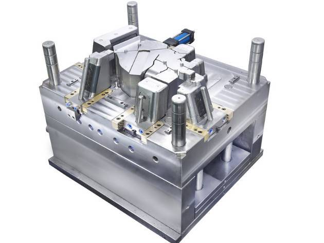
To manufacture a good set of molds, not only a good mold design level and precise processing technology are required, but also "standards" and the concept of "similar" is not allowed.This article lists several acceptance criteria for a good mold. Can you do it?01 Appearance of the mold 1. The content of the mold nameplate is complete, the characters are clear, and the arrangement is neat.2. The nameplate should be fixed on the die foot close to the template and reference corners.The nameplate is fixed reliably and is not easy to peel off.3. The cooling water nozzle should be a plastic block water nozzle, if the customer requires otherwise.4. The cooling water nozzle should not protrude from the surface of the mold base.5. The cooling water nozzle needs to be machined with countersinks. The diameters of the countersinks are 25mm, 30mm, and 35mm. The orifice is chamfered and the chamfers should be consistent.6. The cooling water nozzle should be marked with in and out.7. The marked English characters and numbers should be larger than 5/6, and the position should be 10mm directly below the faucet. The handwriting should be clear, beautiful, neat, and evenly spaced.8. Mold accessories should not affect the lifting and storage of the mold.During installation, there are exposed oil cylinders, faucets, pre-reset mechanisms, etc. below, which should be protected by supporting legs.9. The installation of the support legs should be fixed on the mold base with screws through the support legs, and the excessively long support legs can be fastened to the mold base with the machined external thread posts.10. The size of the ejection hole of the mold should meet the requirements of the specified injection molding machine. Except for small molds, it cannot be ejected with only one center.11. The positioning ring should be fixed and reliable. The diameter of the ring is 100mm and 250mm. The positioning ring is 10~20mm higher than the bottom plate.Unless otherwise requested by the customer.12. The dimensions of the mold should meet the requirements of the specified injection molding machine.13. The installation direction of molds with direction requirements should be marked with arrows on the front or rear formwork. The word "UP" should be next to the arrow. Both the arrow and the text are yellow, and the height of the word is 50 mm.14. There should be no pits, rust, redundant rings, water vapor in and out, oil holes, etc. and defects that affect the appearance on the surface of the mold base.15. The mold should be easy to hoist and transport. When hoisting, the mold parts should not be disassembled, and the lifting ring should not interfere with the faucet, oil cylinder, pre-reset rod, etc.02 Mold material and hardness 1. The mold base should be a standard mold base that meets the standards.2. Mould forming parts and gating system (core, movable and fixed die inserts, movable inserts, shunt cones, push rods, sprue sleeves) are made of materials with performance higher than 40Cr.3. When molding plastics that are easy to corrode to the mold, the molding parts should be made of corrosion-resistant materials, or the molding surface should be anti-corrosion measures.4. The hardness of moulded parts should not be lower than 50HRC, or the hardness of surface hardening should be higher than 600HV.03 Ejecting, resetting, pulling out the ferrule, and taking out parts 1. The ejection should be smooth, without sticking, and without abnormal noise.2. The sloped top surface should be polished, and the sloped top surface should be lower than the core surface.3. The sliding parts should be provided with oil grooves, the surface should be nitrided, and the surface hardness after treatment should be above HV700.4. All rams should have anti-rotation positioning, and each ram should be numbered.5. The ejection distance should be limited by the limit block. 6. The return spring should be a standard part, and the two ends of the spring should not be polished or cut off.7. The slider and the core pulling should have a travel limit, the small slider should be limited by a spring, and a wave screw can be used when the spring is inconvenient to install; the oil cylinder core pulling must have a travel switch.8. The slider core pulling generally adopts the inclined guide column, and the angle of the inclined guide column should be 2°~3° smaller than the angle of the locking surface of the slider.If the stroke of the slider is too long, the cylinder should be used for extraction.9. When the end face of the core-pulling forming part of the cylinder is covered, the cylinder should be equipped with a self-locking mechanism.10. There should be a wear-resistant plate under the large slider with a slider width of more than 150 mm. The wear-resistant plate material should be T8A. After heat treatment, the hardness is HRC50~55, and the wear-resistant plate is 0.05~0.1 mm higher than the large surface. Open the oil tank.11. The ejector rod should not move up and down.12. Add barbs to the ejector rod, the direction of the barbs should be consistent, and the barbs should be easy to remove from the product.13. The matching clearance between the ejector pin hole and ejector pin, the length of the sealing section, and the surface roughness of ejector pin hole should be in accordance with the relevant enterprise standards.14. The product should be easy for the operator to remove.15. When the product is ejected, it is easy to follow the inclined top, and the ejector rod should be grooved or etched.16. The top block fixed on the top rod should be firm and reliable, the non-molded parts around it should be processed with a slope of 3°~5°, and the lower periphery should be chamfered.17. There should be no iron filings in the oil passage holes on the die base.18. The end face of the return rod is flat without spot welding.There is no gasket at the bottom of the embryo head, spot welding.19. The gate plate of the three-plate mold slides smoothly, and the gate plate is easy to open.20. The limit pull rods of the three-plate mold should be arranged on both sides of the mold installation direction, or a pull plate should be added to the mold base to prevent the limit pull rod from interfering with the operator.21. The oil passage and air passage should be smooth, and the hydraulic ejector reset should be in place.22. The bottom of the guide bush should have an exhaust port.23. Do not install the positioning pin without clearance.04 Cooling and heating system 1. The cooling or heating system should be fully unblocked.2. The seal should be reliable, the system should not have leakage under the pressure of 0.5MPa, and it is easy to repair.3. The size and shape of the sealing grooves on the mold base should meet the requirements of relevant standards.4. The sealing ring should be smeared with butter when it is placed, and it should be higher than the surface of the mold base after placement.5. The water and oil channel spacers should be made of materials that are not easily corroded.6. The front and rear molds should adopt centralized water supply and method.05 Gating system 1. The gate setting should not affect the appearance of the product and satisfy the product assembly.2. The cross-section and length of the runner should be designed reasonably, the process should be shortened as much as possible under the premise of ensuring the forming quality, the cross-sectional area should be reduced to shorten the filling and cooling time, and the plastic loss of the gating system should be minimized.3. The partial section of the three-plate die runner on the back of the front formwork should be trapezoidal or semi-circular.4. The three-plate mold has a cut-off handle on the sprue plate, the diameter of the sprue entrance should be less than 3 mm, and there is a 3 mm-deep step recessed into the sprue plate at the ball head.5. The ball head pull rod should be fixed reliably, it can be pressed under the positioning ring, it can be fixed with headless screws, or it can be pressed with a pressure plate.6. The gates and runners should be machined according to the size of the drawings, and manual grinding is not allowed.7. The gate of the point gate should be in accordance with the specification requirements.8. There should be an extension at the front end of the runner as a cold material hole.9. The Z-shaped inversion of the pull rod should have a smooth transition.10. The runners on the parting surface should be circular, and the front and rear molds should not be dislocated.11. There should be no surface shrinkage on the lurking gate on the ejector rod.12. The diameter and depth of the cold material cavity for transparent products should meet the design standards.13. The material handle is easy to remove, the appearance of the product has no gate marks, and there is no residual material handle at the assembly of the product.14. Hook lurking gate, the two parts of the insert should be nitrided, and the surface hardness should reach HV700.06 Hot runner system 1. The wiring layout of the hot runner should be reasonable for easy maintenance, and the wiring numbers should be in one-to-one correspondence.2. The hot runner should be tested for safety, and the insulation resistance to ground should be greater than 2MW.3. The temperature control cabinet, hot nozzle and hot runner should be standard parts.4. The main sprue is connected to the hot runner with a thread, and the bottom surface is contacted and sealed.5. The hot runner is in good contact with the heating plate or heating rod, the heating plate is fixed with screws or studs, and the surface is well fitted.6. The J-type thermocouple should be used and match with the temperature control meter.7. Each group of heating elements should be controlled by a thermocouple, and the position of the thermocouple should be reasonably arranged.8. The nozzle should meet the design requirements.9. The hot runner should be positioned reliably, at least two positioning pins, or fixed with screws.10. There should be a thermal pad between the hot runner and the template.11. The error between the set temperature of the temperature control meter and the actual displayed temperature should be less than ±5°C, and the temperature control should be sensitive.12. The cavity and the nozzle mounting hole should pass through.13. Hot runner wiring should be bundled and covered with a pressure plate.14. There are two sockets of the same size, which should be clearly marked.15. The control wire should be sheathed and not damaged.16. The temperature control cabinet has a reliable structure, and the screws are not loose.17. The socket is installed on the bakelite and cannot exceed the maximum size of the formwork.18. The wires are not allowed to be exposed outside the mold.19. All areas where the hot runner or stencil contacts the wires should have rounded transitions.20. Before the template is assembled, there should be no open circuit or short circuit in all lines.21. All wiring should be properly connected and have good insulation.22. After the template is mounted and clamped, all circuits should be rechecked with a multimeter.07 Forming part, parting surface, exhaust groove 1. The surface of the front and rear molds should not have unevenness, pits, rust and other defects that affect the appearance.2. The insert should be matched with the mold frame, and there should be a gap of less than 1 mm around the rounded corners.3. The parting surface is kept clean and tidy, no hand-held grinding wheel is used to avoid air, and there is no depression in the sealing part.4. The depth of the exhaust groove should be less than the overflow value of the plastic.5. The research and matching of the inserts should be in place, the placement is smooth, and the positioning is reliable.6. The inserts, insert cores, etc. should be positioned and fixed reliably.7. The end face of the ejector pin is consistent with the core.8. There are no defects such as undercuts and chamfers in the front and rear mold forming parts.9. The ejection of the ribs should be smooth. 10. For the products of the multi-cavity mold, the left and right parts are symmetrical, and should be marked with L or R. If the customer has requirements for the position and size, it should meet the customer's requirements, generally in a place that does not affect the appearance and assembly. Plus, the font size is 1/8.11. The locking surface of the mold base should be in place, and more than 75% of the area should be touched.12. The ejector rod should be arranged near the side wall and beside the ribs and bosses, and a larger ejector rod should be used.13. Numbers 1, 2, 3, etc. should be marked for identical parts.14. The touch-through surface, the penetration surface and the parting surface should be researched and matched in place.15. The part of the parting surface sealant should meet the design standards.Molds below medium size are 10~20mm, large molds are 30~50mm, and the rest are machined to avoid voids.16. Skin texture and sandblasting should be uniform to meet customer requirements.17. For products with required appearance, the screws on the products should have anti-shrinkage measures.18. For screw columns with a depth of more than 20 mm, jacking pipes should be used.19. The wall thickness of the product should be uniform, and the deviation should be controlled below ±0.15 mm.20. The width of the ribs should be less than 60% of the wall thickness of the appearance surface. 21. The inserts on the inclined roof and the slider should have a reliable fixing method.22. The front mold is inserted into the rear mold or the rear mold is inserted into the front mold, and there should be inclined surfaces around it to lock and machine to avoid voids.08 Injection molding production process 1. The mold should have the stability of injection molding production and the repeatability of process parameter adjustment within the normal injection molding process conditions.2. The injection pressure during injection molding production should generally be less than 85% of the maximum rated injection pressure of the injection molding machine.3. The injection speed of the mold during injection production, the injection speed of the three-quarter stroke shall not be lower than 10% of the rated maximum injection speed or exceed 90% of the rated maximum injection speed.4. The holding pressure during injection molding production should generally be less than 85% of the actual maximum injection pressure.5. The clamping force of the mold during injection molding production should be less than 90% of the rated clamping force of the applicable model.6. During the injection molding production process, the removal of the product and the nozzle material should be easy and safe (the time generally does not exceed 2 seconds).7. For molds with inserts, the inserts are easy to install and the inserts must be fixed reliably during production.09 Packaging and transportation 1. The mold cavity should be cleaned and sprayed with anti-rust oil.2. Sliding parts should be lubricated.3. The sprue sleeve inlet should be sealed with grease.4. The mold should be installed with a clamping plate, and the specifications meet the design requirements.5. Spare parts and wearing parts should be complete, with detailed list and supplier name.6. The inlet and outlet of mold water, liquid, gas and electricity should be sealed to prevent foreign matter from entering.7. Spray paint on the outer surface of the mold, according to the requirements of the customer.8. The mold should be packaged in moisture-proof, waterproof, and bump-proof packaging, as required by customers.9. Mold product drawings, structural drawings, cooling and heating system drawings, hot runner drawings, supplier details of spare parts and mold materials, instruction manuals, mold test reports, factory inspection certificates, and electronic documents should be complete.
|
|
|
|
|
|
|
|